Alternative hold · Galaxy Tab S6 wall panel

Slide-On Wall Plate

Two printed parts. A plate on the wall with a raised tongue, and a U-frame glued to the back of the tablet that drops down over the tongue and hangs on it. Power still comes through the tablet's own four pads at the bottom edge, from four spring pins in a block on the plate. No magnets, no steel discs, nothing in the USB port.

1 · The idea in one picture

Two parts, and how they meet

Part A · wall plate tongue cable hole pin block, below the tablet edge frame drops over tongue Part B · U-frame, glued to tablet back top bar arm arm open at the bottom, so it slides down over the tongue and rests on it glued to Tablet, seen from behind four pads on the bottom edge land on the pin block Hold and power are separate jobs. The frame and tongue carry the tablet; the pin block at the bottom edge only has to touch the pads.
The frame is a hanger, nothing else. No contacts in it and no ribbon to the USB port, unlike the Headwolf design this borrows the slide-on shape from. The pads on the S6's edge meet spring pins on the plate, the same charging path as before.
2 · Part A

Wall plate, seen from the room

Drawn at 2 px per mm, with the tablet's outline dashed around it for reference. The plate body is 120 × 110 mm and sits from 25 mm below the tablet's top edge to 25 mm above its bottom edge, so it never shows. Only the 40 mm wide stem continues down to the edge to carry the pin block.

tablet outline 244.5 × 159.5, dashed, for reference tongue 80 × 70, 3 mm proud flanks undercut 45° so the frame cannot pull off 4 × countersunk for #8 screws, 8 mm in from the plate's top and bottom edges Ø14 hole through plate and drywall pin block 20 × 8 × 6, slides ±30 mm in the slot, glued once aligned 4 pins · 2.5 mm dia · pitch 3.0 / 3.3 / 3.5 (three blocks printed, use the one that matches) · tips 2 mm above the shoulder 120 110 70 25 25 all mm · plate body 3 thick · everything except the pin block hides behind the tablet
Why the pin block is a separate sliding piece. The pads are centered on the S6's bottom edge to within a millimeter or two, but "within a millimeter or two" is exactly what breaks a pogo connection. The block sits in a slot, you slide it until the pins are dead under the pads with the real tablet in place, then glue it. The print doesn't have to know where the pads are.
3 · Part B

U-frame, seen from the back of the tablet

tablet back · top edge · S Pen groove not shown, the frame clears it top bar 15 · rests on the tongue's top edge arm 15 wide arm 15 wide inside opening 80 wide the tongue fills this four pads, bottom edge, centered 110 100 30 from top edge (set by the glue-up, see §6)
Frame is 3 mm thick, PLA. Its inner edges carry a lip that hooks under the tongue's undercut flanks, so once it's dropped on, pulling straight out from the wall does nothing. Only lifting it 70 mm frees it. The open bottom is what lets it drop on; the top bar is what it hangs from.
4 · Section A–A

Horizontal cut through the tongue and the frame arms

Looking down from above, drawn at 10 px per mm so the interlock is readable.

drywall plate body 3 tongue 3 · wider at the front than at the base arm arm tablet 5.7 · glass toward the room frame glued to tablet here 6.5 The tongue's flanks lean outward. The arms' inner faces lean to match. Once the frame has dropped on, the arms are hooked under the tongue: the tablet cannot be pulled off the wall, only lifted.
Wall to tablet back: about 6.5 mm. Plate 3, tongue 3, half a millimeter of clearance. The frame lives beside the tongue in that same layer, so it adds no thickness. Sliding clearance between tongue and frame is 0.3 mm per side, chosen for FDM printing where outer walls come out slightly large and openings slightly small; if the frame is stiff on the tongue, a few strokes of sandpaper on the tongue's flanks is the intended fix, and if it is loose, a strip of tape on the tongue takes up the slack.
5 · Section B–B

Vertical cut down the center line

Side view through the middle of everything, top of the tablet at the top. Drawn oversize.

drywall hole to the attic 18 AWG up the wall tongue frame top bar, resting on the tongue this carries the tablet's weight arms run down either side of the tongue, out of this cut tablet 5.7 pin block, in its slot, glued after alignment shoulder sits 1 mm below the tablet's edge; pins stand 2 mm proud, so they compress 1 mm the frame carries the weight, the pins only touch; block body reaches back to the wall buck 12→5 V buck converter sits in a pocket on the back of the plate room side → ≈ 6.5 mm, wall to tablet back
Vertical position is set by the frame, not the pins. The frame's top bar rests on the tongue, so the tablet always stops at the same height: its bottom edge 1 mm above the block's shoulder. The pins stand 2 mm above that shoulder, so they are pressed in by 1 mm every time the tablet goes on, which is the working stroke of a 9 mm pogo pin. The block only has to be slid left or right to put the pins under the pads.
6 · On and off

Mounting the tablet, and taking it down

1 · offer up tablet held 80 mm high, frame above the tongue 2 · lower lowering: arms slide down over the tongue's flanks 3 · seated top bar on the tongue, pads on the pins, charging One scale throughout. The tablet is drawn see-through so the frame and tongue behind it are visible; from the room only the tablet and the pin block show.
Down is the reverse. Lift straight up about 70 mm until the frame clears the tongue, then out. One hand. A knock from the side or the front can't move it, because the only free direction is up, against its own weight.
7 · Alignment

How the frame ends up in exactly the right place

You never measure the pad position. The parts find it themselves during glue-up, on the bench, before anything goes on the wall.

  1. Bench setup. Lay the wall plate flat, tongue up, with the pin block loose in its slot and no glue yet.
  2. Tablet on the pins, with a 1 mm shim. Lay the tablet face-up on the plate with a 1 mm spacer between its bottom edge and the block's shoulder: two business cards, or a strip of the 18 AWG wire's insulation. This sets the gap the pins are designed for. Slide the block left or right until the four pin tips sit dead center on the four pads. Now glue the block; let it set with the shim still in place.
  3. Frame on the tongue. With the tablet and shim still in place, drop the U-frame over the tongue from above until its top bar rests on the tongue's top edge. It's now sitting on the tablet's back in the one position that makes everything line up, and the 1 mm shim is what puts the pads at the right height above the pins later.
  4. Glue the frame there. Lift the frame off, apply J-B Weld or a VHB strip to its face, drop it back over the tongue onto the tablet, press, and leave it clamped with a book on top for the cure time.
  5. Check. Lift the tablet off, put it back on. The frame stops on the tongue at the same height every time, so the pads land on the pins every time. Meter the pins for +5 V, and it's ready for the wall.
Pins, wires and the converter. Drill the block's four holes to 2.5 mm with a 3/32" bit. Feed each pin in from the pocket on the block's bottom face, tip first, until its base is flush with the pocket floor (a pin with a base flange stops there on its own); the tip then stands 2 mm above the shoulder. Glue each base. Solder the two outer pins in the pocket, lay the wires in the channel across the block's bottom and up its back, then into the groove on the wall side of the plate, which winds around the slot to the cable hole. Push the 12-to-5 V converter into the wall cavity through the drywall hole before the plate goes on; it hangs on its wires just inside the wall. A dab of black hot glue hides the solder pocket from below.
S Pen groove. The S6's back has a shallow channel where the pen charges. The frame's arms are placed outside it and the top bar sits above it, so the frame glues to flat aluminum. If the groove falls under an arm on your unit, the arm gets a 1 mm relief cut; that's a one-line change in the model.
8 · Numbers

Dimensions and materials

ItemValue
Tablet, Galaxy Tab S6244.5 × 159.5 × 5.7 mm, landscape, pads centered on bottom edge
Wall plate body120 × 110 × 3 mm, PLA, four countersunk #8 holes at (±50, 8 mm in from top and bottom), Ø16 cable hole 10 mm above the plate's bottom edge; top edge 25 mm below the tablet's top, bottom edge 25 mm above the tablet's bottom
Tongue80 × 70 × 3 mm, flanks undercut 45°, top edge 20 mm below plate top
Stem and slot40 mm wide stem from the plate's bottom edge 25 mm down to the tablet's bottom edge; dovetail slot 60 mm long for the pin block
Pin block20 × 8 mm body reaching from 0.5 mm off the wall to 0.2 mm inside the glass plane (11.5 tall), so nothing shows behind it; four holes Ø2.4 (drill to 2.5), pins 2.5 × 9 mm seated in a 1 mm solder pocket so the tips stand 2 mm above the shoulder; shoulder 1 mm below the tablet edge; a 3.5 mm wire channel runs from the pocket across the bottom and up the back face into the plate's groove; printed in three pitches, 3.0 / 3.3 / 3.5 mm
U-frame110 × 100 × 3 mm outside, top bar 15 mm; opening 79.6 mm at the wall face and 85.6 mm at the glue face, cut for the tongue's width at the frame's actual height (0.5 mm above the tongue base) with 0.3 mm clearance per side; glued with its top edge 29 mm below the tablet's top edge
Standoff, wall to tablet backabout 6.5 mm
Lift to remove70 mm straight up, then out
Visible from the roomthe tablet and the 20 mm pin block under its bottom edge; the plate is 62 mm inside the tablet's outline on each side, 25 mm inside top and bottom
Removed from the parts list8 magnets, steel discs
Unchangedpins, glue, 18 AWG wire, Mean Well supply, buck converter, multimeter, anchors, wire nuts, attic junction box and Romex

Both parts print flat with no supports. The plate prints face down; the frame prints on its back. Order in black PLA, 40 percent infill; PETG only if the wall gets direct sun, since PLA softens around 55 °C and a tablet back in shade stays under 40. A print shop quote for the pair should be $25 to $40.

9 · Print files

The three STL files, modeled from these drawings

Modeled in OpenSCAD from the numbers on this page and exported as watertight solids.
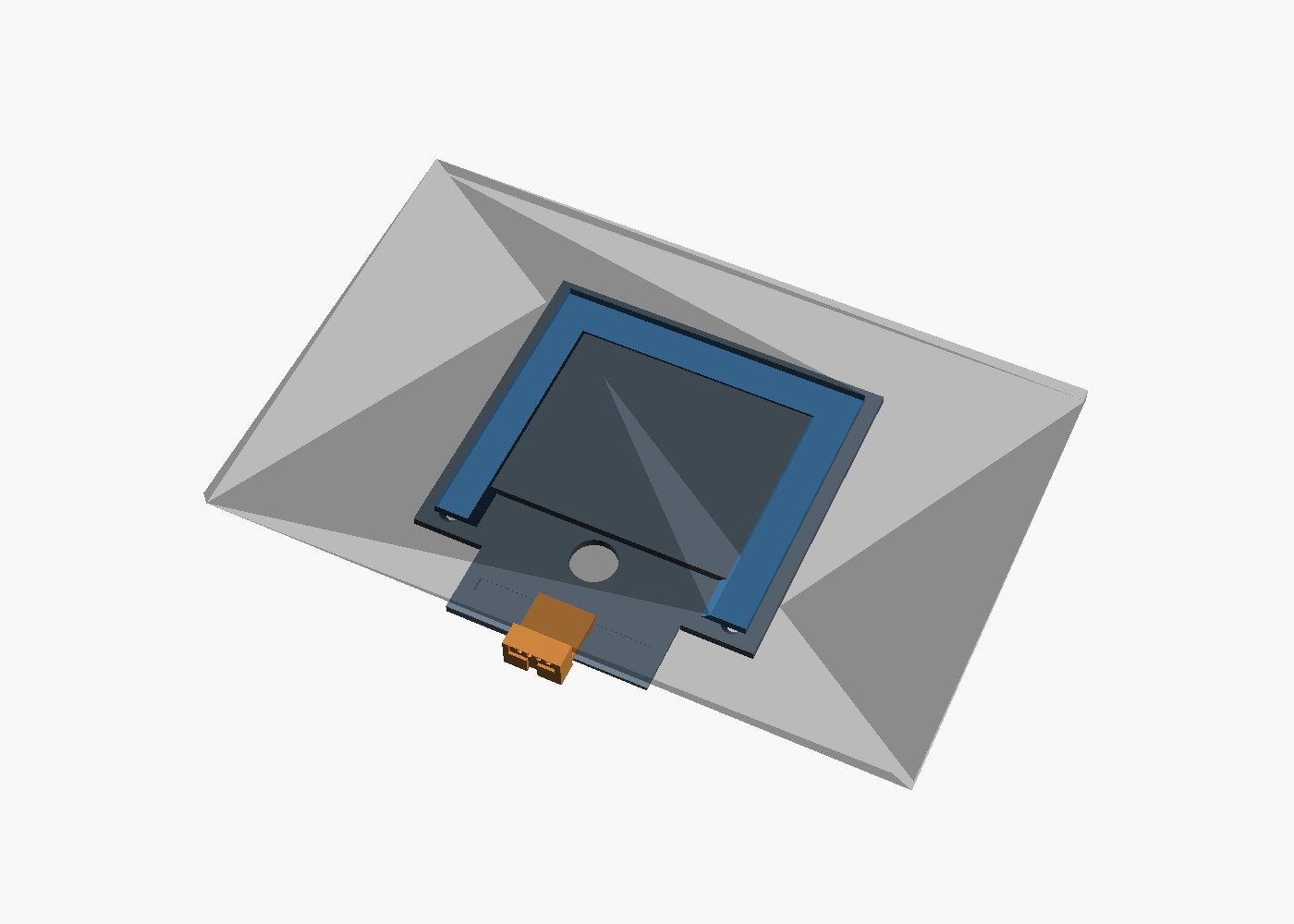
3D render of the assembled mount: wall plate with tongue, U-frame hanging on it, pin block at the bottom, tablet shown translucent
Assembly. Plate in grey, frame in blue hanging on the tongue, pin block in orange under the tablet's bottom edge. The tablet is drawn translucent; from the room only it and the block would show.
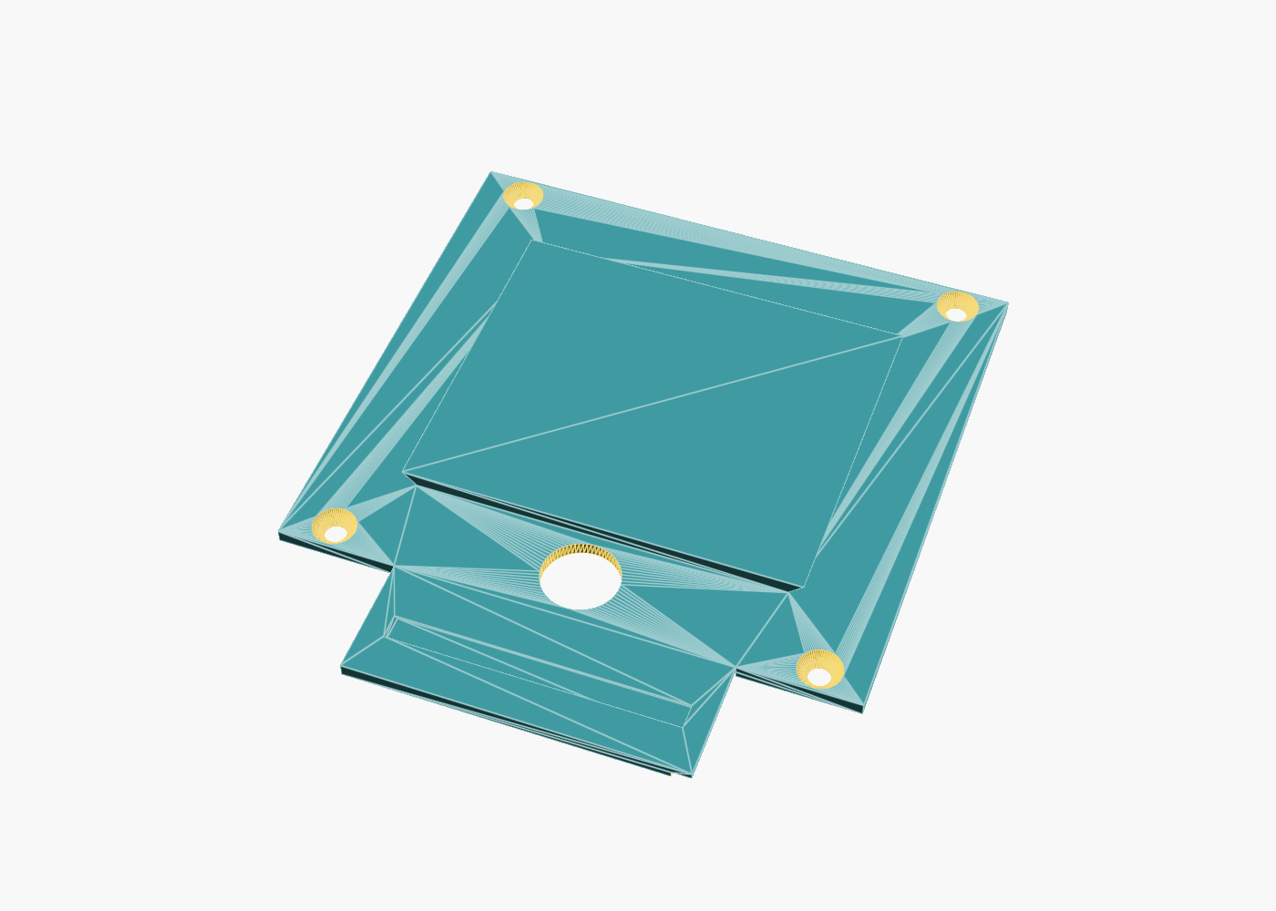
3D render of the wall plate with the raised tongue, four countersunk holes, the cable hole and the dovetail slot across the stem
plate.stl. The raised rectangle is the tongue. Four countersunk holes, the 16 mm cable hole, and the dovetail slot across the stem for the pin block. Prints flat, no supports.
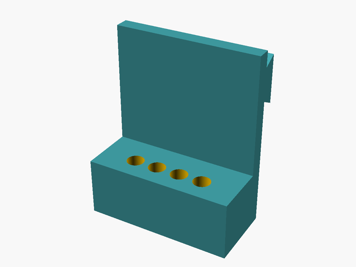
3D render of the pin block standing on its bottom face: four pin holes in the top, a thin bridge rising behind with the dovetail rail at its top
block.stl, three of them. The pad spacing was measured from a photo, so the block comes in 3.0, 3.3 and 3.5 mm pitch. Print all three (it's a two-gram part) and use the one whose pins sit centered on the pads; or measure the outer-pad center distance with calipers, divide by three, and print just that one. Stood on its bottom face so the holes print vertical. Holes are 2.4 mm; drill to 2.5 for the Treedix pins.
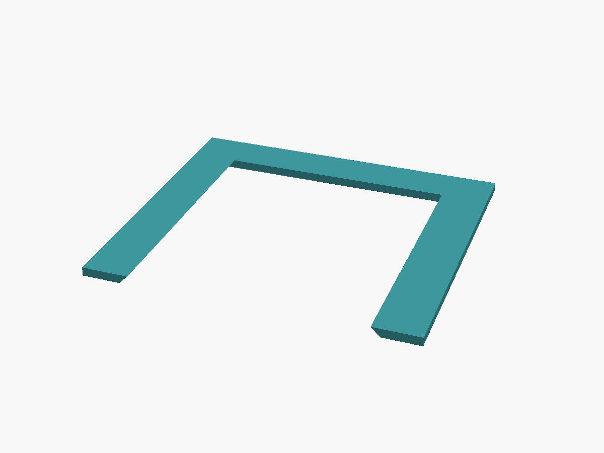
3D render of the U-frame, a flat U shape 3 mm thick
frame.stl. The opening is a dovetail, wider on the face that glues to the tablet, narrower on the wall side, so the arms hook under the tongue. Prints flat, glue face down, no supports.
Tell the shopValue
MaterialPLA, black
Layer height0.2 mm
Infill40 %
Walls3 perimeters
Scale100 %, no fit adjustments
Supportsnone needed; all overhangs are 45°
Orientationas the files are: plate flat, frame flat, block on its bottom face
What the model assumes about the tablet, and what covers it if wrong: pads centered on the bottom edge, covered ±30 mm by the slot; pad pitch about 3.3 mm, covered by the three block variants; pads at mid-thickness of the edge, which the photo shows; body 244.5 × 159.5 × 5.7 mm per Samsung's spec. The S Pen groove on the S6's back runs near one short edge, about 100 mm from the frame's nearest arm, so the frame glues to flat metal.